
- Home
- ProductsBattery Products
Custom lithium & energy-storage solutions — from single cell to full system.
380Wh/kg high energy densityView All Products → Starter BatteryLithium cranking power for engines
 Power Lithium BatteryHigh energy-density battery packs
 Industrial Lithium BatteryRugged cells for industrial use
 UAV BatteryHigh-rate power for drones & UAVs
 CellsCustom Li-ion / LiPo cells
 OEM/ODM and Technical ServicesCustom design & manufacturing
 MaterialsBattery material supply
 EquipmentLab & testing equipment
- Custom Services
- Solution
- Application
- About Us
- Blog
- Contact us

Lithium Battery Manufacturing: From Powder Raw Materials to PACKs — Clarifying the Quality Economics of Battery Cells
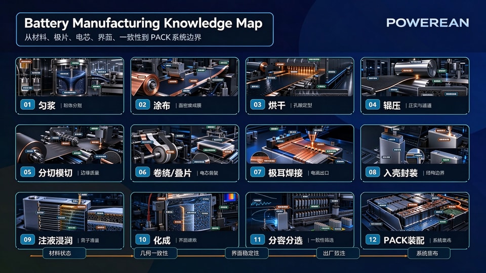
Lithium Battery Manufacturing: From Powder Raw Materials to PACKs — Clarifying the Quality Economics of Battery Cells
In battery manufacturing, from powder materials all the way to PACK, there is one core question to answer: what links all these processes together? Why does the dispersion state in slurry mixing affect coating? Why does areal density variation during coating impact drying? Why do the pores and binder distribution left after drying govern calendering? And how does the electrode condition post-calendering sequentially influence electrolyte filling, formation, grading, and ultimately PACK assembly?
The challenges of battery manufacturing appear on the surface to lie in numerous processes, extensive equipment and abundant parameters. At a deeper level, however, errors from each process propagate and accumulate. The material and geometric states inherited from the preceding process cannot always be fully corrected by the subsequent one; some deviations may even be amplified downstream.
For instance, slurry agglomeration may not immediately render the electrode scrap, yet it can trigger local areal density fluctuation, uneven porosity, inconsistent electrolyte wetting, non-uniform current distribution during formation, and divergence in internal resistance down the line. Most defects along the manufacturing chain do not emerge abruptly — they only become detectable at a certain inspection station.
We can focus on five core accounts here: material account, geometric account, interface account, consistency account and system account.
- The material account covers particles, solvents, conductive network and binders.
- The geometric account covers thickness, areal density, porosity, edges and alignment.
- The interface account covers electrolyte wetting, SEI/CEI films, gas generation and irreversible capacity.
- The consistency account covers capacity, internal resistance, OCV, self-discharge and temperature rise.
- The system account covers series-parallel connection, BMS, cold plates, high-voltage connections, structural constraints and venting paths.
From powder to electrode sheet: transform the material state into geometric state first
In the first half of the manufacturing chain, the core task is to convert powder into controllable electrodes. The slurry mixing stage deals with dispersion, wetting, shearing, agglomeration and rheology; the coating stage handles wet film thickness, areal density, edge morphology and coating window; the drying stage addresses solvent migration, binder enrichment, pore structure and residual solvent; the calendering stage focuses on compaction density, particle contact, porosity and ion channels.
A common feature of these processes is that the morphological profile and electrochemical pathways are shaped simultaneously. Electronic conduction paths must exist between active particles, ionic transport paths must form between particles and electrolyte, mass transfer needs to take place through the thickness of the electrode, and in-plane uniformity must be maintained. Treating the electrode merely as a powder-coated foil easily underestimates the significance of these microstructures.
The variable relationship for coating areal density can be expressed as:
mA,dry ≈ hwet × ρslurry × wsolid
Dry electrode areal loading is jointly determined by wet film thickness, slurry density and solid content, where mA,dry = dry coating areal density, hwet = wet film thickness, ρslurry = slurry density and wsolid = solid content. This formula supports process judgement and reminds us that coating quality is governed by both slurry conditions and equipment process window.
After calendering, the porosity boundary can be expressed as:
ε ≈ 1 - ρelectrode / ρsolid
A higher ρelectrode means more sufficient compaction. However, as porosity ε decreases, electrolyte infiltration and ionic transport may become difficult. High energy density favors high compaction, while high-rate and low-temperature performance require sufficient transport pathways. Manufacturing needs to confine these coupled, trade-off variables within a mass-producible process window, rather than pushing any single metric to its extreme.
When moving from electrode to cell assembly, geometric deviations start to approach the safety margin limits
After slitting and die cutting, the continuous electrode is trimmed into shapes suitable for cell assembly. This step is often regarded as mechanical processing, yet it has a direct impact on safety. Burrs, powder shedding, edge cracks, electrode dimensional variation and tab-region defects may turn into local stress or micro-short circuit risks during subsequent winding/stacking, canning and cycling. Edge quality, seemingly at the millimeter or even micrometer scale, can impinge on the cell’s safety margins.
Winding and stacking organize electrodes, separators and tabs into the cell skeleton. The critical control items here are alignment, tension, wrinkles, separator allowance, edge coverage of electrodes and internal stress. The process window for separator overhang can be expressed as:
Moverhang = (Wsep - Welec) / 2 - |δalign|
Separator width Wsep, electrode width Welec and alignment offset δalign jointly determine the safety margin Moverhang. If this margin is consumed by process variations, subsequent inspection may not fully compensate for it.
Tab welding and current collector connections extract current from inside the cell. Welding energy, penetration depth, spatter, cold joints, pull strength and contact resistance jointly determine local temperature rise under high current. Qweld ≈ ∫ U(t) I(t) dt is merely an energy balance of the process. What we truly need to track is whether energy stably enters the intended bonding zone, rather than being lost to spatter, burn-through, heat-affected zones and local embrittlement.
Can packaging inserts the cell stack into the housing. This stage addresses insulation, clearance, housing constraint, hermetic sealing, gas tightness and subsequent swelling. The housing should not be regarded merely as a protective enclosure; it modifies the cell’s mechanical loading, heat dissipation, pressure relief and safety margins. Long-term stability of a cell depends on both the material system and whether manufacturing places the internal architecture in its correct position.
Electrolyte filling and formation convert the “dry structure” into functional interfaces
Electrolyte filling / wetting is the most underrated step in the manufacturing chain. The amount of electrolyte added is only an input parameter; what truly governs performance is whether the electrolyte penetrates into electrode pores, separator channels, particle interfaces and the deep regions through the electrode thickness. Porosity, tortuosity, compaction density, electrode thickness, vacuum filling, soaking time and temperature all affect the degree of wetting completion.
Wetting depth is governed by capillary penetration relationships. Finer pores, higher tortuosity and greater viscosity slow down wetting. Regions unreached by electrolyte are prone to local polarization and non-uniform interfaces during subsequent formation.
Formation is the first time the cell truly enters an electrochemical operating state. The anode SEI, cathode CEI, initial irreversible capacity, gas evolution, interfacial impedance and voltage plateau all acquire their initial signatures at this stage. These arise from the combined effects of materials, wetting, temperature, pressure and formation protocol and should not be treated as isolated metrics.
At this point in the manufacturing chain, the focus shifts from “physical structure” to “electrochemical interfaces”. Defects from upstream processes are revealed during formation: insufficient wetting induces local polarization, electrode inhomogeneity causes non-uniform current distribution, impurities and moisture trigger side reactions, and packaging issues affect gas evolution and pressure margins. Although formation appears to be merely a charging step, it essentially creates the first interface record for the cell.
Sorting, aging and PACK convert cell-level quality into system-level quality
The purpose of capacity grading, aging and sorting is to separate post-formation cells from those that “work individually” into groups that “work well together”. Qdis = ∫ I(t) dt delivers the capacity budget, and ksd = ΔOCV / Δt reveals self-discharge signatures. Internal resistance, OCV, temperature rise, capacity and post-aging variation collectively determine whether cells can be assembled into the same module. Conformance of individual cells is only an entry requirement; operation within the same group demands consistency.
Consistency is not merely for nominal appearance. In series-connected cells, the weakest unit limits the charge-discharge window of the entire pack. For parallel-connected cells, differences in internal resistance and SOC redistribute current. Hotter regions degrade faster, and the resultant rise in internal resistance further generates more heat. If sorting relies solely on capacity, self-discharge, internal resistance, temperature rise and aging trajectories are easily overlooked.
PACK assembly integrates cells into the system. Once into PACK, issues extend beyond individual cells: high-voltage connections, busbar contact resistance, sense wires, BMS channels, cold plate contact, thermal pad compression, structural preload and pressure relief paths all factor into system safety.
Therefore, the end goal of battery manufacturing is to close the loop across materials, structures, interfaces, inspection and system assembly. “Producing a single cell” is only an intermediate outcome within this loop. Every process parameter set in the factory ultimately manifests in the product as capacity, internal resistance, temperature rise, cycle life, safety, traceability and consistency.
We can review the whole process along three threads:
- Material thread: From slurry mixing, coating, drying and calendering, we examine how particles, conductive agents, binders, pores and transport pathways are established. This thread answers “why the cell can work”.
- Structural thread: From slitting & die cutting, winding/stacking, tab welding and can packaging, we look at how geometric errors, edge quality, current outlets, insulation clearances and housing constraints affect reliability. This thread answers “why the cell may fail”.
- Interface and system thread: From electrolyte filling, formation, capacity grading, aging & sorting, and PACK assembly, we analyze how electrolyte, SEI/CEI, consistency, BMS, high-voltage connections and thermal management transform individual cells into a system. This thread answers “why qualified cells still require management”.
The underlying logic of battery manufacturing is essentially converting invisible variables into inspectable, traceable and releasable engineering metrics. Agglomeration in slurry, pores inside electrodes, separator overhang at edges, penetration depth at welds, electrolyte wetting depth, side reactions during formation, self-discharge during aging, and contact resistance within PACK — these variables should not be inferred merely from final outcomes. The earlier we capture them along the manufacturing chain, the lower the downstream cost. Quality is not about over-stringent requirements on individual points, but precise process control and scientific balance across the whole picture. We exercise refined management and control over every critical link in production. With systematic thinking to coordinate all quality factors, we strike a balance among stability, safety and cost-effectiveness, delivering long-term balanced and reliable overall quality. This also reflects Powerean’s consistent commitment to protecting customer interests.
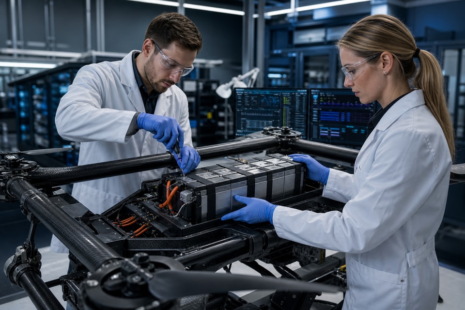

Let's build the right battery for your application.
Powerean delivers dependable battery packs, energy-storage systems and intelligent BMS solutions for demanding applications.