
- Home
- ProductsBattery Products
Custom lithium & energy-storage solutions — from single cell to full system.
380Wh/kg high energy densityView All Products → UAV BatteryHigh-rate power for drones & UAVs
 Power Lithium BatteryHigh energy-density battery packs
 Industrial Lithium BatteryRugged cells for industrial use
 Energy Storage Batteries and SystemsGrid & residential ESS
 CellsCustom Li-ion / LiPo cells
 OEM/ODM and Technical ServicesCustom design & manufacturing
 MaterialsBattery material supply
 EquipmentLab & testing equipment
 - Custom Services
- Solution
- Application
- About Us
- Blog
- Contact us

Custom Battery Solutions
Battery packs engineered around your voltage, capacity and operating requirements.

Reliable Power for UAV Missions
High-rate lithium batteries built for payload, endurance and dependable flight performance.

Scalable Energy Storage
Reliable battery systems for efficient commercial and industrial energy storage.
Products
Explore our energy-storage solutions engineered for reliable, efficient and scalable applications.
Energy Storage Systems
Reliable and scalable energy-storage solutions for commercial and industrial applications.
Explore solutions →Battery Modules & Packs
Engineered battery modules and packs designed for safety, performance and long service life.
View products →Battery Management Systems
Intelligent BMS solutions for real-time monitoring, protection and optimized battery performance.
Learn more →Custom Energy Solutions
Tailored battery and energy solutions built around your voltage, capacity and application requirements.
Talk to us →Custom Battery Solutions
From application requirements to final delivery, our engineering team turns your specification into a dependable energy solution.
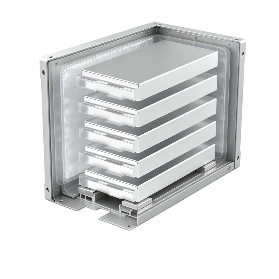
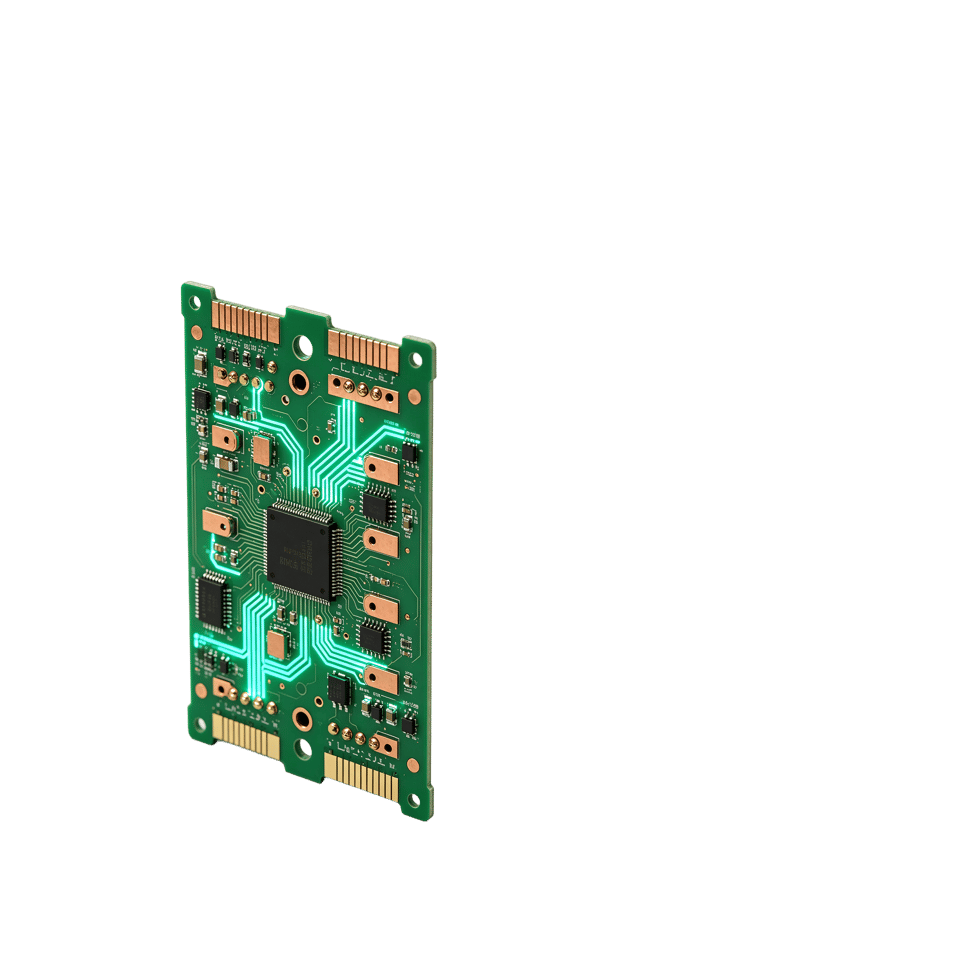
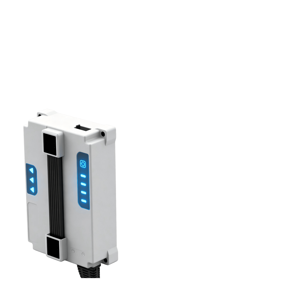

Requirement Analysis
Define application, voltage, capacity and environment.
Solution Design
Engineer the electrical, mechanical and thermal concept.
Prototype Development
Build and validate the first functional sample.
Battery Customization
Finalize cells, BMS, structure and interfaces.
Testing & Validation
Verify safety, performance and reliability.
Mass Production
Launch controlled, traceable manufacturing.
Quality Inspection
Conduct final inspection before shipment.
Delivery & Support
Deliver globally with lifecycle technical support.
Featured Products
Explore selected energy-storage solutions engineered for demanding applications.
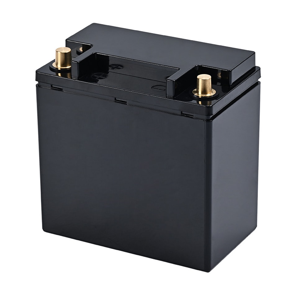
Starting Power Supply4
Explore product →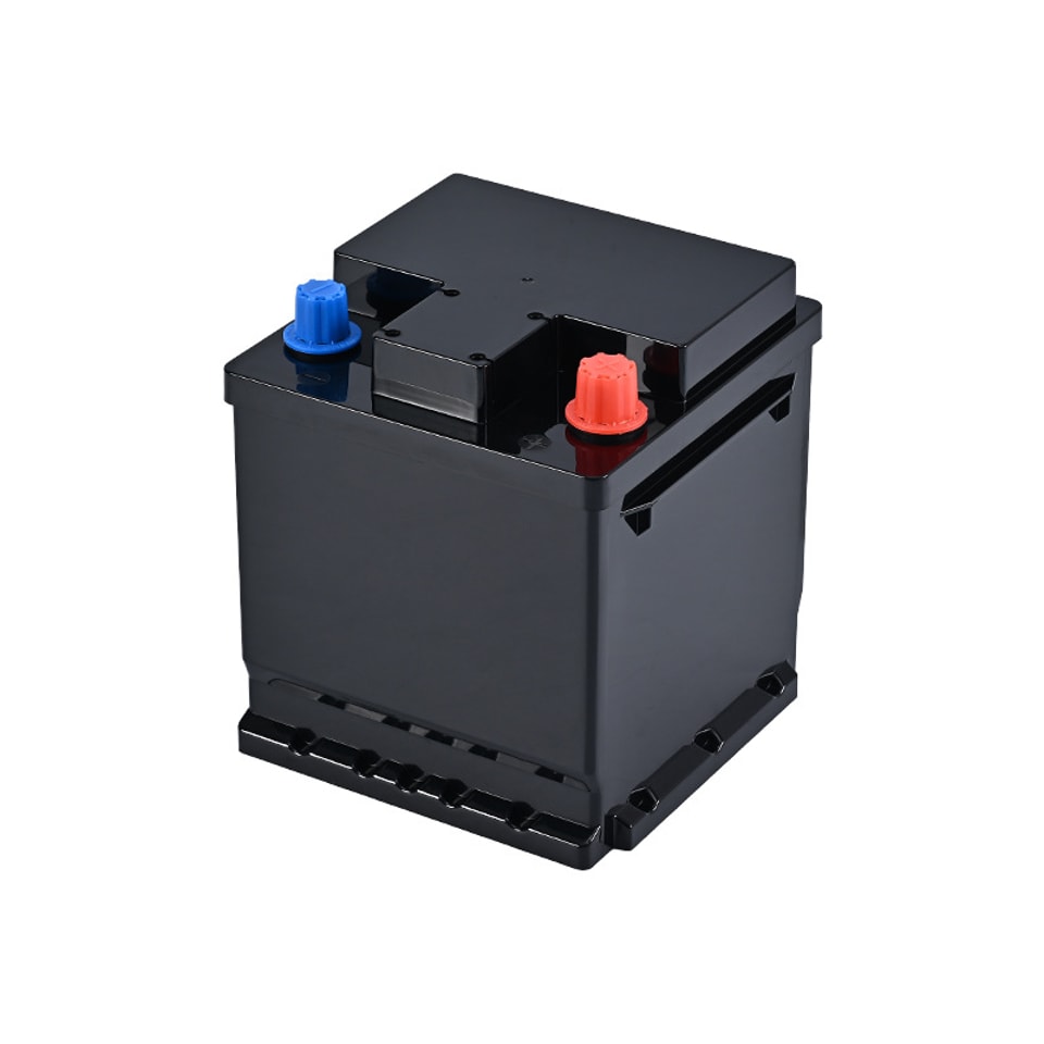
Starting Power Supply3
Explore product →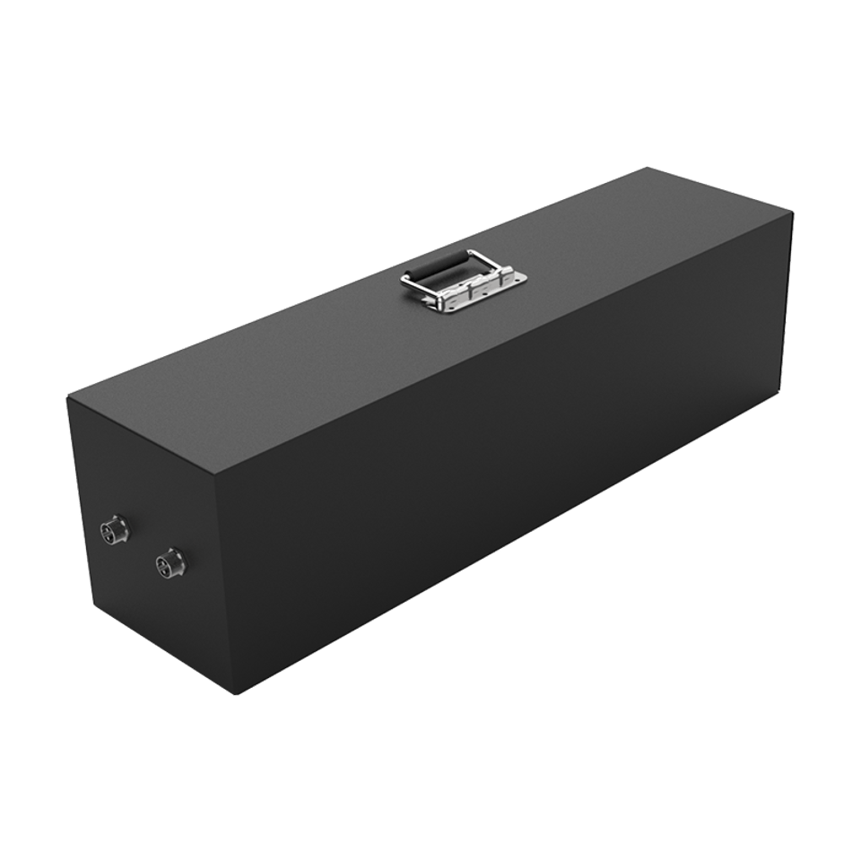
AGV Communication Battery
Explore product →
AGV Industrial Equipment Battery
Explore product →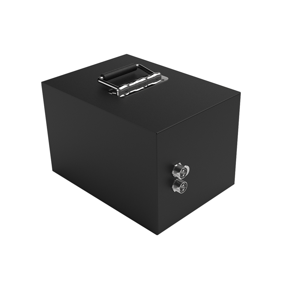
AGV Robot Battery
Explore product →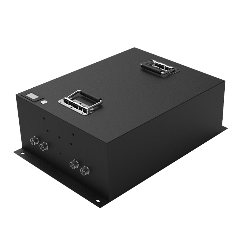
AGV Photovoltaic Cleaning Robot
Explore product →
AGV Medical Equipment Battery
Explore product →
AGV Backup Power Supply
Explore product →Battery Applications
Engineered energy solutions for mobility, industry and demanding operating environments.

World-Class Professional Team
Our team is composed of seasoned experts and senior engineers from renowned industry leaders such as CATL, BYD, Panasonic, and Gotion. Leveraging decades of experience in advanced battery manufacturing and intelligent process control, we provide cutting-edge solutions tailored to our customers’ needs, ensuring every project is delivered to the highest standards of quality, efficiency, and reliability.
About Us →News & Insights
Explore practical perspectives on battery technology, energy storage and reliable power solutions.

How High-Rate Lithium Batteries Support Reliable UAV Operations
Reliable UAV operation depends on more than selecting a battery with an attractive energy rating. Multirotor aircraft and other electrically powered unmanned platforms impose fast-changing loads during takeoff, climbing, maneuvering, gust correction, payload operation, and landing. A high-rate lithium battery must therefore deliver current with controlled voltage sag while remaining within appropriate electrical and thermal limits. The most useful engineering approach is to evaluate the battery, aircraft, mission, and operating environment as one system.Why UAV Loads Are Different from Steady LoadsA UAV propulsion system rarely draws constant current. Hover may establish the mission baseline, but acceleration, aggressive attitude correction, and recovery from wind disturbances can create short demand peaks. If cell impedance, interconnect resistance, or state of charge causes excessive voltage drop, the flight controller may encounter an early low-voltage threshold even though some stored energy remains. This can shorten usable flight time and reduce the reserve available for a safe return.High-rate capability describes the ability to support elevated discharge current, but the label alone is not a complete design value. Engineers should examine the intended continuous current, pulse magnitude, pulse duration, duty cycle, minimum voltage requirement, and pack temperature. The correct question is not simply whether a pack has a high C-rate; it is whether the complete pack can support the aircraft’s real load profile with suitable margin throughout the planned mission.Translate the Flight Profile into Battery RequirementsBattery selection should begin with measured or conservatively estimated propulsion demand. Motor and propeller choice, aircraft mass, payload, altitude, wind, and control strategy all influence current. A mission model should include takeoff, climb, cruise or hover, task execution, return, and landing rather than relying on a single average-current figure.Define continuous and transient current at pack level.Identify the minimum usable bus voltage for propulsion and avionics.Include connector, cable, fuse, and protection-device resistance.Reserve energy for route deviation, headwind, and landing.Evaluate both beginning-of-life and aged-pack behavior.Energy and power must be balanced. Adding capacity can increase endurance, but added mass also raises propulsion demand. Conversely, a lighter pack may improve efficiency while offering less energy or less thermal mass. Iterative aircraft-level modeling is more reliable than optimizing battery specifications in isolation.Manage Voltage Sag, Heat, and IntegrationInternal resistance converts current into heat and contributes to terminal-voltage reduction. Because resistive heating rises approximately with the square of current, short high-current events can be thermally important when repeated frequently. Cell selection matters, but pack architecture also deserves attention. Welds, busbars, leads, connectors, and contact interfaces should be sized for the expected load without introducing unnecessary resistance or local hot spots.Temperature sensing should represent the most relevant thermal locations, not merely the easiest point to access. Airflow around an exposed pack may cool surfaces unevenly, while an enclosed fuselage can retain heat after landing. Charging a pack before it has returned to an appropriate temperature can add avoidable stress. Mechanical integration should also prevent abrasion, movement, crushing, and vibration damage while allowing safe installation and removal.Validate Reliability with Mission-Based TestingBench testing is most valuable when it reproduces actual demand. A programmable load profile can reveal voltage sag, temperature rise, cell-group imbalance, and protection behavior before flight trials. Testing should cover different states of charge and relevant ambient conditions. Instrumented ground runs and controlled flight tests can then confirm that laboratory assumptions reflect the aircraft.Operational discipline is equally important. Record pack identity, cycles or operating time, charge data, unusual heating, physical condition, and flight performance. Establish clear criteria for inspection, quarantine, and retirement. Trends such as increasing voltage sag or growing cell imbalance can be more informative than a single pass/fail measurement.Conclusion: Engineer the Battery Around the MissionHigh-rate lithium batteries can support dependable UAV operation when their power capability, usable energy, thermal behavior, protection strategy, and mechanical integration are matched to the mission. Reliability comes from realistic load definition, adequate margin, representative validation, and consistent operating procedures—not from one headline specification.Planning a UAV battery system? Share your aircraft voltage, peak and continuous current, payload, target flight profile, space constraints, and environmental conditions with our team. We can help review the application requirements and discuss a practical battery-pack design direction for engineering evaluation.
Read more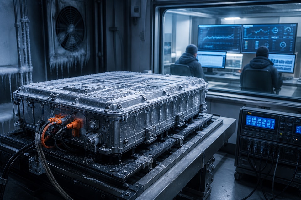
Designing Lithium Battery Systems for Reliable Sub-Zero Performance
Sub-zero operation changes how a lithium battery behaves. Electrochemical reactions slow, ionic transport becomes more difficult, internal resistance rises, and the same load can produce greater voltage sag than it would at room temperature. These effects do not mean that every cold-environment application requires the same solution. They mean the battery system must be designed around a defined temperature range, load profile, charging method, enclosure, and duty cycle.Understand What Cold Temperature ChangesAt low temperature, reduced power capability can become the immediate system constraint even when the pack still contains energy. A load step may pull terminal voltage toward an equipment cutoff, causing an early shutdown. Once the battery warms or the load is removed, voltage may recover, but that recovery should not be mistaken for full usable capacity under operating conditions.Charging deserves separate attention. The acceptable charging conditions of a cell chemistry and design are not automatically the same as its discharge conditions. Attempting to charge when the cells are colder than their permitted range can create safety and durability concerns. The battery management strategy should therefore distinguish cell temperature from ambient temperature and enforce charging rules based on verified cell conditions.Build Requirements from the Real Duty CycleA useful specification begins with the coldest expected cell temperature, not only the weather forecast. Storage duration, wind exposure, enclosure insulation, nearby heat sources, and operating schedule all affect the initial condition. Engineers should map the complete sequence: cold soak, startup, peak load, steady operation, idle periods, charging, and shutdown.Define minimum, typical, and maximum ambient conditions.Specify continuous current, pulse current, and pulse duration.Identify the equipment’s minimum input voltage and startup demand.Separate cold discharge requirements from cold charging requirements.Include reserve for aging, manufacturing variation, and heat loss.Clarify whether warm-up power comes from the battery or an external source.This sequence often exposes competing goals. Insulation can retain useful heat during operation but may slow cooling in warmer conditions. An internal heater can improve cell temperature before high load or charging, but it consumes energy and requires control logic. Capacity added to provide margin also adds volume, mass, and cost.Coordinate Thermal, Electrical, and Mechanical DesignCold-performance design is a system task. Cell selection should be supported by current paths with low and consistent resistance. Cables, connectors, fuses, busbars, and switching devices must be evaluated at low temperature because materials, contact behavior, and flexibility can change. Voltage sensing should remain accurate enough for protection and state estimation across the intended range.If heating is used, temperature uniformity matters. A sensor near a heater may report an acceptable value while cells farther away remain cold. Heater placement, insulation, thermal interfaces, and multiple sensing points can reduce this risk. Control logic should define when heating starts, the target range, the permitted load during warm-up, and the conditions under which charging may begin. Mechanical materials should also tolerate thermal cycling without creating pressure points, seal failures, or condensation pathways.Use Controls and Validation to Preserve MarginA battery management system can apply temperature-dependent current limits, block charging outside approved conditions, and report information to the host equipment. State-of-charge estimation may require compensation because voltage response and usable energy change with temperature and load. Conservative control thresholds should be based on tested behavior rather than room-temperature assumptions.Validation should combine cell or module characterization with complete-pack testing. Cold-soak the system long enough for temperatures to stabilize, then apply representative startup and operating profiles. Record individual cell-group voltages, pack voltage, current, sensor temperatures, heater consumption, and protection events. Repeat relevant tests at different states of charge and after suitable aging simulations or service accumulation. Verify transitions as well: moving equipment from cold storage into a warmer, humid environment can create condensation that the enclosure and operating procedure must address.Conclusion: Design for Temperature at System LevelReliable sub-zero performance depends on more than choosing a cell described as suitable for low temperatures. The electrical load, thermal architecture, charging controls, sensing, enclosure, and operating procedure must work together. Clear environmental requirements and representative cold-soak testing help engineers understand true usable power and energy before deployment.Developing a battery system for cold conditions? Send us your temperature range, current profile, charging scenario, installation constraints, and expected duty cycle. Our team can help review the key engineering inputs and discuss an appropriate architecture for further design and validation.
Read more
What an Intelligent BMS Adds to Industrial Battery Reliability
In an industrial lithium battery system, the battery management system is the layer that converts cell measurements into operating decisions. An intelligent BMS can monitor conditions, enforce limits, estimate battery state, record events, and communicate with the host equipment. These functions can improve reliability, but only when sensing, algorithms, protection hardware, communications, and application requirements are engineered as one coordinated system.From Basic Protection to System AwarenessBasic protection responds when voltage, current, or temperature crosses a defined boundary. An intelligent BMS adds context by observing trends, applying operating-state logic, and sharing information with the machine controller or energy-management system. For example, warning thresholds can allow the host to reduce load before a protection limit forces disconnection. This coordinated response may preserve process continuity while keeping the battery within its intended operating envelope.Intelligence should not be confused with unlimited prediction. State of charge and state of health are estimates influenced by cell behavior, temperature, load history, sensor accuracy, and model assumptions. Their practical value depends on calibration and validation across the application’s real operating range. A clearly defined uncertainty and fallback strategy is more useful than a precise-looking number without known confidence.Measurements and Controls That MatterReliable decisions begin with reliable data. Cell-group voltages, pack current, and temperatures are common inputs, but sensor quantity and placement should reflect the pack architecture. A single temperature reading may not represent cells near a current connection, enclosure wall, heater, or cooling path. Likewise, current-measurement offset can accumulate into meaningful state-of-charge error over long operating periods.Monitor cell-group and pack-level voltage with appropriate accuracy.Measure current across expected charge, discharge, and standby ranges.Place temperature sensors at thermally significant locations.Coordinate contactor control, pre-charge, fusing, and fault response.Use balancing according to the cell configuration and duty cycle.Record actionable events with timestamps and relevant operating data.Protection design should consider both detection and safe actuation. The BMS may command contactors or semiconductor switches, but the complete current-interruption path must be suitable for system voltage, fault current, and load characteristics. Pre-charge logic is particularly important when industrial equipment has large input capacitance. The sequence should prevent excessive inrush while confirming that expected voltage behavior occurs.Communication Enables Coordinated ReliabilityIndustrial batteries often operate as part of a larger machine. CAN, RS-485, or another interface can provide state, limits, warnings, and diagnostic information to the host. The communication specification should define message timing, units, scaling, valid ranges, startup behavior, timeout handling, and fault priorities. If communication is lost, both the BMS and host need a deterministic safe response.Dynamic charge and discharge limits can help the host adapt to temperature, state of charge, or other operating constraints. However, command authority must be explicit. Engineers should define whether the BMS sets mandatory limits, provides advisory values, or directly disconnects the pack. They should also consider network robustness, termination, grounding, electromagnetic compatibility, and firmware compatibility during service replacement.Diagnostics, Data, and Lifecycle ManagementEvent logs can reduce troubleshooting time when they capture context rather than only a fault code. Useful records may include minimum and maximum cell-group voltage, current, temperatures, state estimates, contactor state, and the sequence leading to an event. Data volume and retention should match service needs, with attention to access control and version traceability.Firmware is part of the safety and reliability configuration. Changes should follow controlled requirements, review, testing, release identification, and rollback planning. Field updates, if supported, require secure authorization and protection against incomplete installation. Diagnostic tools should make it possible to identify hardware and firmware versions without encouraging uncontrolled parameter changes.Validation should include normal operation, boundary conditions, sensor faults, communication loss, contactor anomalies, pre-charge failure, and power interruption. Hardware-in-the-loop testing can exercise repeatable fault scenarios, while pack-level testing confirms actual electrical and thermal behavior. Acceptance criteria should connect directly to the industrial duty cycle and hazard analysis.Conclusion: Intelligence Must Be Engineered and VerifiedAn intelligent BMS adds value by turning measurements into coordinated limits, protection, communication, and service information. Its contribution to industrial battery reliability depends on accurate sensing, transparent control logic, robust interfaces, disciplined firmware management, and representative validation. Intelligence is most effective when it helps the complete machine respond predictably to both normal changes and faults.Evaluating BMS requirements for an industrial battery? Share your pack voltage, current profile, contactor architecture, communication protocol, environmental range, and host-control needs. Our team can help organize the technical requirements and discuss a suitable BMS and battery-system integration approach.
Read moreBuilding Energy Solutions Together
We work with leading technology and manufacturing partners to deliver dependable energy-storage solutions worldwide.















Contact Us
Let's build the right battery for your application.
Powerean delivers dependable battery packs, energy-storage systems and intelligent BMS solutions for demanding applications.